Space Shuttle
NASA's Space Shuttle, officially called Space Transportation System (STS), is the spacecraft currently used by the United States government for its human spaceflight missions. At launch, it consists of a rust-colored external tank (ET), two white, slender solid rocket boosters (SRBs), and a winged orbiter (the space shuttle in the narrow sense). The orbiter carries astronauts and payload such as satellites or space station parts into low earth orbit. Usually, five to seven astronauts ride in the orbiter. The payload capacity is 50,000 lb (22,700 kg). When the orbiter's mission is complete, it fires its orbital maneuvering thrusters to drop out of orbit and re-enters the Earth's atmosphere. During the descent and landing, the shuttle orbiter acts as a glider and makes a completely unpowered ("dead stick") landing. Five spaceworthy orbiters were built, of which three remain.
The Shuttle is the first orbital spacecraft designed for partial reusability. It carries payloads to low Earth orbit, provides crew rotation for the International Space Station (ISS), and performs servicing missions. The orbiter can also recover satellites and other payloads from orbit and return them to Earth, but this capacity has not been used often. However, it has been used to return large payloads from the ISS to Earth, as the Russian Soyuz spacecraft has limited capacity for return payloads. Each Shuttle was designed for a projected lifespan of 100 launches or 10 years' operational life. The man responsible for the design of the STS was Maxime Faget, who had also overseen the Mercury, Gemini and Apollo spacecraft designs. The crucial factor in the size and shape of the Shuttle Orbiter was the requirement that it be able to accommodate the largest planned spy satellites, and have the cross-range recovery range to meet classified USAF missions requirement for a one-around abort for a polar launch. Factors involved in opting for 'reusable' solid rockets and an expendable fuel tank included the desire of the Pentagon to obtain a high-capacity payload vehicle for satellite deployment, and the desire of the Nixon administration to reduce the costs of space exploration by developing a spacecraft with reusable components.
Six shuttles have been built, five of which were spaceworthy. The first orbiter, Enterprise, was not built for actual space flight, and was used only for testing purposes. Enterprise was followed by four operational space shuttles: Columbia, Challenger, Discovery and Atlantis. Challenger was destroyed on launch in 1986, and Endeavour was built as a replacement. Columbia was destroyed on re-entry in 2003.
NASA announced in 2004 that the Space Shuttle will be retired in 2010 and replaced by the Orion, a new vehicle that is designed to take humans to the Moon and beyond.
3ds MAX 2008
Create rich and complex design visualization. Generate realistic characters for a top-selling game. Bring 3D effects to the big screen. Autodesk®
3ds Max® 2008 3D modeling, animation, and rendering software helps design visualization professionals, game developers, and visual effects artists maximize their productivity by streamlining the process of working with complex scenes.
Highlights
Achieve stunning results in less time with Autodesk® 3ds Max® software. 3ds Max 2008 dramatically improves your productivity by streamlining the process of working with complex scenes. This is achieved through significant performance improvements—in areas such as viewport interaction, interactive transform and material assignment—as well as through the addition of new, artist-friendly UI and scene management features. The release also marks the launch of Review, a toolset that delivers interactive previewing of shadows, the 3ds Max sun/sky system, and Architectural and Design material settings.
In addition, 3ds Max 2008 delivers enhanced support for complex pipelines and workflows—a new, integrated MAXScript ProEditor makes extending and customizing 3ds Max easier than ever. Plus, enhanced DWG™ file-linking and data support strengthen interoperability with applications such as AutoCAD® 2008, AutoCAD® Architecture 2008, and Revit® Architecture 2008 software products. Finally, the release contains numerous Biped improvements, including new ways of layering character motion and exporting it to game engines, as well as tools that give animators new levels of flexibility with regards to their Biped rigs.
Scene Explorer Scene Management
Review
MAXScript ProEditor
Enhanced DWG Import
Artist-Friendly Modeling Options
Biped Enhancements
Expanded Platform Support
Routers
Router
This article is about a computer networking device. For the kind of rotating cutting tool, see wood router. For the type of network router found in many homes, see residential gateway.
Cisco 1800 Router
Cisco 1800 Router
A router is a device that determines the proper path for data to travel between different networks, and forwards data packets to the next device along this path.[1] They connect networks together; a LAN to a WAN for example, to access the Internet. Some units, like the Cisco 1800 (pictured), are available in both wired and wireless models.
Function
Nortel ERS 8600
Nortel ERS 8600
A more precise definition of a router is a computer networking device that interconnects separate logical subnets. Routers are now available in many types, though all are fundamentally doing the same job. A router is a computer whose software and hardware are usually tailored to the tasks of routing and forwarding, generally containing a specialized operating system (e.g. Cisco's IOS or Juniper Networks JunOS or Extreme Networks XOS), RAM, NVRAM, flash memory, and one or more processors. High-end routers contain many processors and specialized Application-specific integrated circuits (ASIC) and do a great deal of parallel processing. However, with the proper software (such as XORP or Quagga), even commodity PCs can act as routers.
Routers connect with two or more logical subnets, which do not necessarily map one-to-one to the physical interfaces of the router.[2]
The term switch or layer 3 switch or network switch often is used interchangeably with router, but switch is really a marketing term without a rigorous technical definition (though a switch is commonly understood as a network hub with switched ports, which might or might not also perform additional routing functions).
Chassis systems like the Nortel MERS-8600 or ERS-8600 routing switch, allow for a wide variety of LAN, MAN, METRO, and WAN port technologies or other connections that are customizable.
Routers operate in two different planes [3]:
* Control Plane, in which the router learns the outgoing interface that is most appropriate for forwarding specific packets to specific destinations,
* Forwarding Plane, which is responsible for the actual process of sending a packet received on a logical interface to an outbound logical interface.
Routers are like intersections whereas subnets are like streets and hosts like houses
Routers are like intersections whereas subnets are like streets and hosts like houses
Control Plane processing leads to the construction of what is variously called a routing table or routing information base (RIB). The RIB may be used by the Forwarding Plane to look up the outbound interface for a given packet, or, depending on the router implementation, the Control Plane may populate a separate Forwarding Information Base (FIB) with destination information. RIBs are optimized for efficient updating with control mechanisms such as routing protocols, while FIBs are optimized for the fastest possible lookup of the information needed to select the outbound interface.
The Control Plane constructs the routing table from knowledge of the up/down status of its local interfaces, from hard-coded static routes, and from exchanging routing protocol information with other routers. It is not compulsory for a router to use routing protocols to function, if for example it was configured solely with static routes. The routing table stores the best routes to certain network destinations, the "routing metrics" associated with those routes, and the path to the next hop router.
Routers do maintain state on the routes in the RIB/routing table, but this is quite distinct from not maintaining state on individual packets that have been forwarded.
For the pure Internet Protocol (IP) forwarding function, router design tries to minimize the state information kept on individual packets. Once a packet is forwarded, the router should retain no more than statistical information about it. It is the sending and receiving endpoint that keeps information on such things as errored or missing packets.
Forwarding decisions can involve decisions at layers other than the IP internetwork layer or OSI layer 3. Again, the marketing term switch can be applied to devices that have these capabilities. A function that forwards based on data link layer, or OSI layer 2, information, is properly called a bridge, or layer 2 switch. A physical device called a router may also have the capability to forward based on information at other layers, if it has software that can make decisions at these other layers.
[[Image:Cisco-rs1.jpg|thumb|right|Cisco CRS-1 Carrier Routing System
Cisco 7600 Enterprise Routers
Cisco 7600 Enterprise Routers
Routers may provide connectivity inside enterprises, between enterprises and the Internet, and inside Internet Service Providers (ISP). The largest routers (for example the Cisco CRS-1 or Juniper T1600) interconnect ISPs, are used inside ISPs, or may be used in very large enterprise networks. An example of an enterprise router would be the Cisco 7600 (pictured above). The smallest routers provide connectivity for small and home offices (for example the Linksys BEFSR41).
Routers intended for ISP and major enterprise connectivity will almost invariably exchange routing information with the Border Gateway Protocol. RFC 4098[4] defines several types of BGP-speaking routers:
* Provider Edge Router: Placed at the edge of an ISP network, it speaks external BGP (eBGP) to a BGP speaker in another provider or large enterprise Autonomous System (AS).
* Subscriber Edge Router: Located at the edge of the subscriber's network, it speaks eBGP to its provider's AS(s). It belongs to an end user (enterprise) organization.
* Inter-provider Border Router: Interconnecting ISPs, this is a BGP speaking router that maintains BGP sessions with other BGP speaking routers in other providers' ASes.
* Core router: A router that resides within the middle or backbone of the network rather than at its periphery.
Within an ISP: Internal to the provider's AS, such a router speaks internal BGP (iBGP) to that provider's edge routers, other intra-provider core routers, or the provider's inter-provider border routers.
"Internet backbone:" The Internet does not have a clearly identifiable backbone, as did its predecessors. See default-free zone (DFZ). Nevertheless, it is the major ISPs' routers that make up what many would consider the core. These ISPs operate all four types of the BGP-speaking routers described here. In ISP usage, a "core" router is internal to an ISP, and used to interconnect its edge and border routers. Core routers may also have specialized functions in virtual private networks based on a combination of BGP and Multi-Protocol Label Switching (MPLS)[5].
History
The very first device that had fundamentally the same functionality as a router does today, i.e a packet switch, was the Interface Message Processor (IMP); IMPs were the devices that made up the ARPANET, the first packet switching network. The idea for a router (although they were called "gateways" at the time) initially came about through an international group of computer networking researchers called the International Network Working Group (INWG). Set up in 1972 as an informal group to consider the technical issues involved in connecting different networks, later that year it became a subcommittee of the International Federation for Information Processing. [7]
These devices were different from most previous packet switches in two ways. First, they connected dissimilar kinds of networks, such as serial lines and local area networks. Second, they were connectionless devices, which had no role in assuring that traffic was delivered reliably, leaving that entirely to the hosts (although this particular idea had been previously pioneered in the CYCLADES network).
The idea was explored in more detail, with the intention to produce an actual prototype system, as part of two contemporaneous programs. One was the initial DARPA-initiated program, which created the TCP/IP architecture of today. [8] The other was a program at Xerox PARC to explore new networking technologies, which produced the PARC Universal Packet system, although due to corporate intellectual property concerns it received little attention outside Xerox until years later. [9]
The earliest Xerox routers came into operation sometime after early 1974. The first true IP router was developed by Virginia Strazisar at BBN, as part of that DARPA-initiated effort, during 1975-1976. By the end of 1976, three PDP-11-based routers were in service in the experimental prototype Internet. [10]
The first multiprotocol routers were independently created by staff researchers at MIT and Stanford in 1981; the Stanford router was done by William Yeager, and the MIT one by Noel Chiappa; both were also based on PDP-11s. [11] [12] [13] [14]
As virtually all networking now uses IP at the network layer, multiprotocol routers are largely obsolete, although they were important in the early stages of the growth of computer networking, when several protocols other than TCP/IP were in widespread use. Routers that handle both IPv4 and IPv6 arguably are multiprotocol, but in a far less variable sense than a router that processed AppleTalk, DECnet, IP, and Xerox protocols.
In the original era of routing (from the mid-1970s through the 1980s), general-purpose mini-computers served as routers. Although general-purpose computers can perform routing, modern high-speed routers are highly specialized computers, generally with extra hardware added to accelerate both common routing functions such as packet forwarding and specialised functions such as IPsec encryption.
Still, there is substantial use of Linux and Unix machines, running open source routing code, for routing research and selected other applications. While Cisco's operating system was independently designed, other major router operating systems, such as those from Juniper Networks and Extreme Networks, are extensively modified but still have Unix ancestry.
Other changes also improve reliability, such as redundant control processors with stateful failover, and using storage having no moving parts for program loading. As much reliability comes from operational techniques for running critical routers as it does to the router design itself. It is the best common practice, for example, to use redundant uninterruptible power supplies for all critical network elements, with generator backup for the batteries or flywheels of those power supplies.
A router is an Intermediate System (IS) which operates at the network layer of the OSI reference model. Routers may be used to connect two or more IP networks, or an IP network to an internet connection.
A router consists of a computer with at least two network interface cards supporting the IP protocol. The router receives packets from each interface via a network interface and forwards the received packets to an appropriate output network interface. Received packets have all link layer protocol headers removed, and transmitted packets have a new link protocol header added prior to transmission.
The router uses the information held in the network layer header (i.e. IP header) to decide whether to forward each received packet, and which network interface to use to send the packet. Most packets are forwareded based on the packet's IP destination address, along with routing information held within the router in a routing table. Before a packet is forwarded, the processor checks the Maximum Transfer Unit (MTU) of the specified interface. Packets larger than the interface's MTU must be fragmented by the router into two or more smaller packets. If a packet is received which has the Don't Fragment (DF) bit set in the packet header, the packet is not fragmented, but instead discarded. In this case, an ICMP error message is returned to the sender (i.e. to the original packet's IP source address) informing it of the interface's MTU size. This forms the basis for Path MTU discovery (PMTU).
The routing and filter tables resemble similar tables in link layer bridges and switches. Except, that instead of specifying link hardware addresses (MAC addresses), the router table sepcify network (IP addresses). The routing table lists known IP destination addresses with the appropraite network interface to be used to reach that destiantion. A default entry may be specified to be used for all addresses not explicitly defined in the table. A filter table may also be used to ensure that unwanted packets are discarded. The filter may be used to deny access to particular protocols or to prevent unauthorised access from remote computers by discarding packets to specified destination addresses.
A router forwards packets from one IP network to another IP network. Like other systems, it determines the IP network from the logical AND of an IP address with the associated subnetwork address mask. One execption to this rule is when a router receives an IP packet to a network broadcast address. In this case, the router discards the packet. Forwarding broadcast packet can lead to severe storms of packets, and if uncontrolled could lead to network overload.
A router introduces delay (latency) as it processes the packets it receives. The total delay observed is the sum of many components including:
- Time taken to process the frame by the data link protocol
- Time taken to select the correct output link (i.e. filtering and routing)
- Queuing delay at the output link (when the link is busy)
- Other activities which consume processor resources (computing routing tables, network management, generation of logging information)
The router queue of packets waiting to be sent also introduces a potential cause of packet loss. Since the router has a finite amount of buffer memory to hold the queue, a router which receives packets at too high a rate may experience a full queue. In this case, the router ahs no other option than to simply discard excess packets. If required, these may later be retransmitted by a transport protocol.
Routers are often used to connect together networks which use different types of links (for instance an HDLC link connecting a WAN to a local Ethernet LAN). The optimum (and maximum) packet lengths (i.e. the maximum transmission unit (MTU)) is different for different types of network. A router may therefore uses IP to provide segmentation of packets into a suitable size for transmission on a network.
Associated protocols perform network error reporting (ICMP), communication between routers (to determine appropriate routes to each destination) and remote monitoring of the router operation (network management).
The operation of a simple modern router is described on a separate page. If you want to know how the router actually works click HERE.
Neděle, 28. říjen 2007
| Documents |
|
| Presentations |
|
| Animation | ||
| TWO ENGINES UNDER ONE HOOD Think of a computer chip�s core--the central processing unitor CPU--as an engine. See animation video [mpeg, 272 MB] | ||
|


The Processor
The processor (really a short form for microprocessor and also often called the CPU or central processing unit) is the central component of the PC. It is the brain that runs the show inside the PC. All work that you do on your computer is performed directly or indirectly by the processor. Obviously, it is one of the most important components of the PC, if not the most important. It is also, scientifically, not only one of the most amazing parts of the PC, but one of the most amazing devices in the world of technology.
The processor plays a significant role in the following important aspects of your computer system:
- Performance: The processor is probably the most important single determinant of system performance in the PC. While other components also play a key role in determining performance, the processor's capabilities dictate the maximum performance of a system. The other devices only allow the processor to reach its full potential.
- Software Support: Newer, faster processors enable the use of the latest software. In addition, new processors such as the Pentium with MMX Technology, enable the use of specialized software not usable on earlier machines.
- Reliability and Stability: The quality of the processor is one factor that determines how reliably your system will run. While most processors are very dependable, some are not. This also depends to some extent on the age of the processor and how much energy it consumes.
- Energy Consumption and Cooling: Originally processors consumed relatively little power compared to other system devices. Newer processors can consume a great deal of power. Power consumption has an impact on everything from cooling method selection to overall system reliability.
- Motherboard Support: The processor you decide to use in your system will be a major determining factor in what sort of chipset you must use, and hence what motherboard you buy. The motherboard in turn dictates many facets of your system's capabilities and performance.
This section discusses many different aspects of this important component in full detail, and concludes with a look at the major processor families used on the PC platform, from the original IBM PC processors to the latest technology. Note that the explanations of how the processor works and what its characteristics are, is kept mostly separate from the information on particular processors. This is done to keep information organized and easier to find. However, I also include summary tables in each of the description sections showing how the various processors fare in that particular area. This shows the evolution of the technology and lets you more easily compare processors in various ways.
Středa, 10. říjen 2007
Switches
Multiway switching
Multiway switching is a method of connecting switches in groups so that any switch can be used to connect or disconnect the load. This is most commonly done with lighting.
Two locations

2. Second method
3. Labelling of switch terminals
Switching a load on or off from two locations (for instance, turning a light on or off from either end of a flight of stairs) requires two SPDT switches. There are two basic methods of wiring to achieve this, and other not recommended.
In the first method, mains is fed into the common terminal of one of the switches; the switches are then connected through the L1 and L2 terminals (swapping the L1 and L2 terminals will just make the switches work the other way round), and finally a feed to the light is taken from the common of the second switch. A connects to B or C, D connects to B or C; the light is on if A connects to D, i.e. if A and D both connect to B or both connect to C.
The second method is to join the three terminals of one switch to the corresponding terminals on the other switch and take the incoming supply and the wire out to the light to the L1 and L2 terminals. Through one switch A connects to B or C, through the other also to B or C; the light is on if B connects to C, i.e. if A connects to B with one switch and to C with the other.
Wiring needed in addition to the mains network (not including protective earths):
First method:
- double wire between both switches
- single wire from one switch to the mains
- single wire from the other switch to the load
- single wire from the load to the mains
Second method:
- triple wire between both switches
- single wire from any position between the two switches, to the mains
- single wire from any position between the two switches, to the load
- single wire from the load to the mains
If the mains and the load are connected to the system of switches at one of them, then in both methods we need three wires between the two switches. In the first method one of the three wires just has to pass through the switch, which tends to be less convenient than being connected. When multiple wires come to a terminal they can often all be put directly in the terminal. When wires need to be joined without going to a terminal a crimped joint, piece of terminal block, wirenut or similar device must be used and the bulk of this may require use of a deeper backbox.
Using the first method, there are four possible combinations of switch positions: two with the light on and two with the light off.
-
Off On 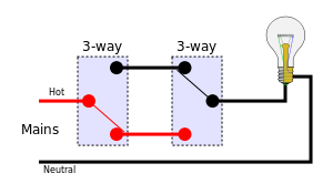
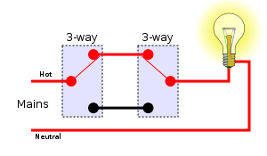


An unrecommended method

If there is a hot (a unique phase) and a neutral wire in both switches and just one wire between them where the light is connected (as in the picture), you can then solve the two way switch problem easily: just plug the hot in the top from switch, the neutral in the bottom from switch and the wire that goes to the light in the middle from the switch. This in both switches. Now you have a fully functional two way switch.
This works like the first method above: there are four possibilities and just in two of them there is a hot and a neutral connected in the poles of the light. In the other ones, both poles are neutral or hot and then no current flows because the potential difference is zero.
The advantage of this method is that it uses just one wire to the light, having a hot and neutral in both switches. The reason why this is not recommended is because in both switches there will be hot and neutral wires near to each other, which can lead to a short circuit more easily than in the other methods.
More than two locations

1. First method
2. Second method
3. Labelling of switch terminals
For more than two locations, the two cores connecting the L1 and L2 of the switches must be passed through an intermediate switch (as explained above) wired to swap them over. Any number of intermediate switches can be inserted, allowing for any number of locations.
Wiring needed in addition to the mains network (not including protective earths):
First method:
- double wire along the sequence of switches
- single wire from the first switch to mains
- single wire from the last switch to the load
- single wire (neutral) from load to mains
Second method:
- double wire along the sequence of switches
- single wire from first switch to last switch
- single wire from anywhere between two of the switches to the mains
- single wire from anywhere between the same two switches to the load
- single wire (neutral) from load to mains
Using the first method, there are eight possible combinations of switch positions: four with the light on and four with the light off.
-
Off On 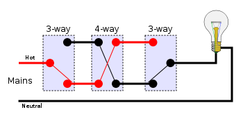
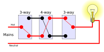
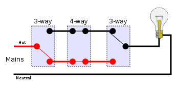
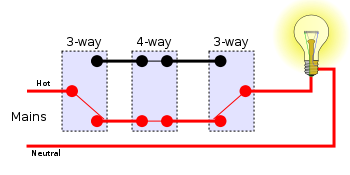

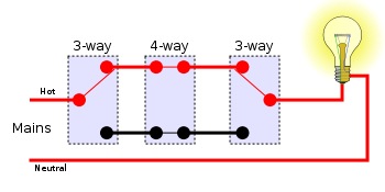

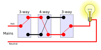


As mentioned above, the above circuit can be extended by using multiple 4-way switches between the 3-way switches to extend switching
Žádné komentáře:
Okomentovat